free website stats program fretting and metal erosion on stock compensator | Page 3 | Harley Davidson Forums

fretting and metal erosion on stock compensator

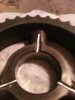
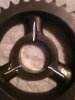
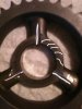
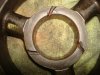
.010" is not deep enough in my opinion. There is plenty of material to work with. I went much deeper (.100") and funneled the beginning of the groove to try any collect oil better. Make the grooves wide. At least .125"

The factory grooved pressure washer already has about .010" grooves in it and it did not work.

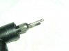
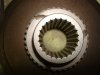
Hoop - I coulda sworn I read this somewhere, but what did you use to cut the grooves into your sprocket? Dremel w/ a carbide cutting wheel, stone or what? I'm getting ready to cut these grooves into my sprocket and getting things together - thanks
 
but what did you use to cut the grooves into your sprocket? Dremel w/ a carbide

I used a 1/8" cylindrical ball nose carbide bur mounted in a Dremel. Grainger part # 2RPX1. Once you cut through the hard surface, it cuts fast.
 

Attachments

  • bits 004.jpg
    bits 004.jpg
    21.2 KB · Views: 49
I am interested in this but I am having a hard time understanding what part and where you are adding grooves to the SE Compensator part.
I need a picture I think. Can anyone help me with a link or something?

Yesterday when I went to start my scoot, it took 3 attempt for some reason and there was a loud "clack" that sounded like it was comming from the compensator. I have 43K on the clock and I have never had anything done to it (stock compensator). I keep the oil (Spectro Primary) fresh and up to the correct level as well as keep the rpms above 2000, but I am wondering if there is some wear occuring. I have previously read about how the SE compensator was a marked improvement over the stock model, but this is the first that I am seeing that it has issues.

Thanks for any help.:D
 
Here is a couple of pics of mine after I finished the grooves.
 

Attachments

  • SE Comp I.jpg
    SE Comp I.jpg
    30.9 KB · Views: 92
  • SE Comp II.jpg
    SE Comp II.jpg
    29.9 KB · Views: 91
Here is a couple of pics of mine after I finished the grooves.

Thank you, that really helps!

One question: Would it be possible to score groove in a shallow "C" shape on the inner most circle such that as the piece rotates it would pump oil in?

I tried to draw some lines on this photo to describe what I mean:
 

Attachments

  • SE%20Comp%20II curve.JPG
    SE%20Comp%20II curve.JPG
    31.1 KB · Views: 51
This is what I tried on the last one. Will see how it works out down the road.
Also have the grooves down the spline but can't find that pic.
 

Attachments

  • DSC02037.JPG
    DSC02037.JPG
    111.1 KB · Views: 71
  • DSC02038.JPG
    DSC02038.JPG
    89.3 KB · Views: 62
This is what I tried on the last one. Will see how it works out down the road.
Also have the grooves down the spline but can't find that pic.

If you can find eventually find that pic I would appreciate it.
If the groves are in the correct rotation direction, it seems like it should work while rotating.

I think the straight lined grooves would work better when the sitting still to allow oil to drip down inside, but may actually allow oil to be flung out, centrifugally, when spinning.

Thanks again, the photos really help me understand the issue!
 
Back
Top