You are using an out of date browser. It may not display this or other websites correctly.
You should upgrade or use an alternative browser.
You should upgrade or use an alternative browser.
Timing is way out... no seeming adjustment
- Thread starter oowf
- Start date
oowf
Member
Same question as UltraT asked above. I can't remember whether you had the nose cone off and the cam out of the cam chest. If so, I would suggest going back in to double check all the alignment marks.
TQ
Thanks for this one... TQuentin1 and UltraT...
I did have the cone off.. Had to take it off to drill out the broken stud and to re-tap for a larger stud...
I don't remember taking any of the gears out but I do remember seeing the dots and they WERE NOT meeting each other. Didn't think much about that at the time as I DIDN'T remove any of the gears and I just figured the engine needed to be in a particular orientation for them to all be in alignment (for lack of a better word).
I will go out now and get into that... remove the cone etc... to check, but that brings up a new question. How do I know the engine is in the proper place (rotation? orientation?) to align those dots on the gears?
My skype id is TQuentin1
Give me a shout.
In case I do not get to talk to you, check out the info I provided to Catwoman here:
Cam, pinion gear, TDC-timing prob--HELP! - Harley Davidson Community
See #4 and #13 especially.
TQ
Give me a shout.
In case I do not get to talk to you, check out the info I provided to Catwoman here:
Cam, pinion gear, TDC-timing prob--HELP! - Harley Davidson Community
See #4 and #13 especially.
TQ
Last edited:
hippie13
Active Member
this is quite interesting. im not a bike mechanic lol but with cyl #1 at tdc and on the compression stroke ( valves closed ) is the way to check that the marks line up.
if they dont turn the crankshaft 1full turn ( maybe on the wrong stroke ) and check the marks again.
sounds like mayb somebody put a cam in and didnt line things up proper? or some people will move it a tooth off for different preformance reasons ;-) just my 2cents lol good luck man
Posted via Mobile Device
Normally in aligning the EVO, the key is to start with the pinion gear. Rotate the rear wheel with the plugs out (and the tranny in 4th or 5th) until the timing mark on the gear is straight up (12 o'clock). Then assemble the camshaft so its timing mark mates with the drive gear's, and then insert the breather so its mark lines up with the other one on the camshaft. That is it.
In your case, you do not want to gut the cam chest, so rotate the rear wheel until the timing mark on the camshaft gear is straight down, and the timing mark on the drive gear is close, but a tooth or so off. If it is WAY off, keep rotating the camshaft another 360 deg. With the camshaft gear at the 6 o'clock position, the breather gear timing mark should align to the mark on the camshaft gear.
Now comes the tricky part. See which way the drive gear moves as you move the rear wheel forward and backwards. Realign the camshaft gear straight down again. Making sure that the camshaft DOES NOT drop down, remove the drive gear and rotate the rear wheel just enough for the drive gear to line up with the camshaft mark. Button it up and try it.
TQ
Last edited:
oowf
Member
Again, thank you for your time this evening (your time). I immediately went and pulled the cone. No problem with the cam shaft coming loose. However, the long slash mark on the cam and the punch mark on the cam seem different than we discussed. For a mark on the cam gear to align with the breather gear mark, it has to be the "punch" mark, not the elongated one and the elongated one needs to align with the Pinion gear mark.
Can you please clarify? Also on the pinion gear there is no mark and there is a nut on the end of it which we didn't discuss... Is there something I am missing? For sure there is no mark on the pinion gear... of course I haven't taken it off yet... waiting for your reply. Is it possible someone put it on backwards? Is that possible?
Thank You
Thank You... I am trying everything... I have uploaded two pics of my gears and how they line up... See my post to TQuentin1.
Cheers!
Hi... I tried to get back to you on Skype but then I looked at my watch and I'm sure you were cutting Zsssssss. Sorry about that.
Well, I got the cone off and check the marks and they do line up perfectly. I only went around one time assuming that once was enough. Am I correct in that?
I have attached two pics for you to see what I have in case you spot something amiss.
Thank you again! I will not button this back up until I hear back as to if there is something else I should do while inside this case.
Much regards!

and

Thank You again!
Not sure why the pics aren't showing... maybe it's because the site I have them on has user name and password... it doesn't matter.. nothing there all that secure... the user name is "nbell" and the pass is "what2222" both without the quotes. You should be able to cut and paste the URL into your browser and they should pull up. Let me know if they don't.
Can you please clarify? Also on the pinion gear there is no mark and there is a nut on the end of it which we didn't discuss... Is there something I am missing? For sure there is no mark on the pinion gear... of course I haven't taken it off yet... waiting for your reply. Is it possible someone put it on backwards? Is that possible?
Thank You
Thank You... I am trying everything... I have uploaded two pics of my gears and how they line up... See my post to TQuentin1.
Cheers!
Hi... I tried to get back to you on Skype but then I looked at my watch and I'm sure you were cutting Zsssssss. Sorry about that.
Well, I got the cone off and check the marks and they do line up perfectly. I only went around one time assuming that once was enough. Am I correct in that?
I have attached two pics for you to see what I have in case you spot something amiss.
Thank you again! I will not button this back up until I hear back as to if there is something else I should do while inside this case.
Much regards!
and
Thank You again!
Not sure why the pics aren't showing... maybe it's because the site I have them on has user name and password... it doesn't matter.. nothing there all that secure... the user name is "nbell" and the pass is "what2222" both without the quotes. You should be able to cut and paste the URL into your browser and they should pull up. Let me know if they don't.
Last edited by a moderator:
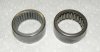
However a question here... what is a new "Torrington". Some type of bearing I assume but how would I know if what I have is new or whether it is a Torrington? For sure it sounds like something I should change...
Actually we still say Torrington, but in Oct of 2002, Timkin bought the Torrington Co. from Ingersoll-Rand. Details!!
The inner support bearing for the inside end of the camshaft is a needle bearing. HD in its infinite wisdom (and cost savings methods) uses some cheap bearing from INA that are NOT robust enough. If that inner bearing goes, it will scatter bits of bearing grade steel throughout the oil system potentially doing ALL kinds of mischief. So I would suggest that at the first opportunity, the INA bearing be exchanged for a "Torrington" bearing. See pix below (Torrington left, INA right).
I am not sure it is worth all the time and effort JUST to change out the inner camshaft bearing, but it should be part of any project where the cam chest is gonna be disassembled anyway. George's Garage, JIMS, even HD (probably the JIMS) make a puller and installer for the bearing. The puller is a definite need. But the installer may be a work around it necessary. But note - the EVO bearings are a different size then the '99-'06 TC which are different from the '07-Present TC. So get the puller (and installer if you want it) for the EVO!
TQ
I am breaking my own rule here with a follow-on post, but I will merge them later tonight.
Nathan,
Look at the pdf attachment below. You want to check continuity between the VOES and the Ignition Module. That is the V/W colored wire (don't remember if that is violet w/white trace, or violet trace on white wire!! but whatever) from the connector you plugged your spliced connector into to the Ignition Module connector pin #6. Also check continuity on the Black wire side of the VOES connector to ground.
While you are doing this, you might as well check the continuity of the Sensor Plate sending unit to the Ignition Wire. Pins A, B and C at the Sensor Plate go to Ignition Module pins 3, 5 and 2 respectively. You can see the wire color codes on the schematic.
If all the wiring checks out, I suggest slappin' the beast together. You can try going through the static timing procedure described in the book on pages 8-9 to 8-10. If that works, great. If not, try going to Dynamic by starting it up, warming it up for a few minutes so it will run without the enricher, and then following the procedure on pages 8-10 to 8-11.
Lettuce know.
TQ
Attachments
Last edited:
oowf
Member
Where I stand with this situation at the present with the following items checked and verified.
1.) Pulled cone and with the transmission in 4th, rotated the real wheel until all three marks liked up. Just perfect. Cam Gear to Pinion Gear and Cam Gear to Breather Gear. All line up just fine.
2.) Put the cone back on... incidentally here... the gasket went South on me when I removed the cone so I made another one out of paper as close to the thickness of the original as I could... remember, I am in China so can't run down and buy a new gasket but one is on the way from the States.. and when I got the bike running the cone got hotter than it normally does. Would that mean the gasket I made is not such a good idea?
3.) Have installed a new VOES valve with new hose properly attached.
4.) Have installed a new sensor plate properly connected using the old Deutch connector with no problem there.
5.) At this point I set the #1 Piston at top dead center with the vertical hash mark on the flywheel in the center of the view port on the left side of the engine. Installed a test cable between the Deutch connector the Sensor Plate connects to and checking the voltage between the Green White and Black White wire, (static timing) I can get a drop in volts from 5 volts to the 0 - 1 volts but to do so, even with then new sensor plate the sensor plate has to be in the retarded position PAST the place where the sensor plate stud would normally stop the plate's rotation if it were in place. In other words... if the sensor plate is in the normal range (rather then in an "over retarded" position, I stay at 5 volts regardless of how far I move the plate in the "Advance" or "Retarded" direction. By the way, in the super retarded direction (where I could successfully get the voltage drop), the bike would not start at all.
6.) Next I went ahead and set the sensor plate at a very advanced position and got the bike to start and warmed it up. I set the RPM to 1400 and tried to see the single punch timing dot on the flywheel through the plastic view port and never did see it regardless of where I positioned the sensor plate. I then made the same attempt at 900 RPM, 1000 RPM, 1100 RPM, 1200 RPM and 1300 RPM and never did see the mark. This bike has three marks on the flywheel.. a single long dash, two punched dots (the manual says to ignore) and one punched dot. I never saw any of those three even though I have painted them with several coats of acrylic white paint I got from a model shop. My timing light works fine on my car so I think it is OK for this application.
At this point I have a very lost and "sunk" feeling. Not sure what is next! I will continue to report on this as I go...
Cheers!
I am now getting into doing what electrical checks I can do.. continuity and such related to both the VOES valve and the Sensor Plate.
Thursday evening - Oct 15, 2009 - China time...
Spent the entire day chasing down any problems with all the wiring related to the cam sensor, VOES valve and the ignition module. Checked the following in the listed order.
1.) VOES ground - excellent
2.) VOES action - checked by taking the vacuum hose off at the carb, connected my ohm meter red wire to the violet wire at the ignition module connector and the ohm meter black wire to ground on the chassis. Sucked on the vacuum hose and obtained a good ohm reading.
3.) Checked continuity from VOES switch (each wire.. both ground and hot) from the actual switch to the ignition module connector and got a good ohm reading.
4.) Checked for continuity and "good ground" on the cam sensor wiring as well as the cam sensor plate for ground with good results.
Prior to doing all the above I removed the tanks and carb as well as intake manifold to both simplify the "checking" work on the wiring system.
I went ahead and checked most of the electrical systems and even discovered that this bike is wired for but not supplied with an emergency flasher.
Total results to the last two days of spending many happy hours with my ride are this...
I can not set static timing. I cannot set dynamic timing. Cam Gear, Pinion Gear and Breather Gear are all lined up properly for 0 sea level use.
Cam sensor is new and good. VOES valve is also new and good.
Just can't get the bike to run decent now and simply can't figure out why.
Tomorrow I will clean and rebuild the carb as much as I can. I will wait to reassemble the carb and intake until my new intake seal set arrives which were ordered and shipped two weeks ago.
Questions remaining are this.
Is there a way to check the ignition module its self?
And if I can't find any joy with this timing should I go to an after market ignition system and if so what brand would be recommended.
Thank you for your help!... Wishing to ride again!
Last edited by a moderator:
Checking the module would be difficult without the proper test equipment for the module and not knowing the parameters of the module would make it even more impossible. Replacing it would be the only accurate way of telling but possibly you could go with a points plate and points setup that would be the easiest and cheapest.