free website stats program Adjuster cam "slop" on baggers with this system | Harley Davidson Forums

Adjuster cam "slop" on baggers with this system

TQuentin1

Well-Known Member
Staff member
Moderator
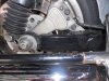
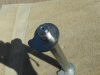
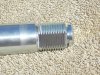
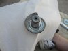
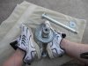
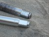
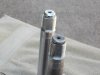
I have carefully inspected the axle and adjuster cam on my '03 UC when changing out the rear tire and brake pads this past week. What I have found is that there is CONSIDERABLE slop (probably a 1/16" or 3/32") in the adjuster cam movement on the axle profile that fits through the cam. Attached is the section from my manual that describes the belt adjusting procedure. You can picture what I am describing by looking at the graphic on the right although it does not show the exact problem.

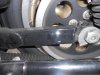
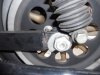
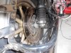
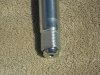
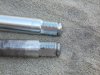
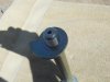
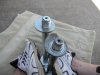
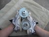
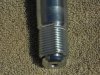
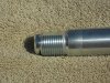
The problem is that the profile is cut in the threaded end of the axle where the cone nut tightens on the axle. This means that the adjuster cam is being turned by the profile that is cut in the threads where there is less metal to apply force to the cam. Consequently, the cam has compressed or deformed the edge of this profile on the axle threads. I went to the HD shop and bought a new cam hoping that it played a role in the slop I have noticed in this cam/axle interface. Unfortunately, this did not help. It is the axle and more specifically the threaded portion of the axle that is damaged. I have ordered a new axle from Zanotti's, but it has not arrived.

The consequence to this problem is that I do not think the axle is being pulled back evenly and in alignment as it is designed to do when taking out the deflection in the belt. After mounting the wheel and tightening everything up with the old axle and adjuster cam installed, I took the bike for a ride up to Lufkin and back. There was a discernible wobble although NOT severe around 65-70mph. I believe this is due to an alignment problem caused by the damage to the profile in the threaded portion of the axle where it makes contact with the inside profile of the adjuster cam. Poor design by HD. They should have made the profile on the axle in the non-threaded portion of the axle, and used a cone nut that had a relief to account for any protrusion of the non-threaded axle (or even just a 1/8" thick washer!!

I'll go out later and see if I can measure any misalignment of the axle.

TQ
 

Attachments

  • Adjusting belt tension UC.pdf
    2 MB · Views: 157
Wow, that is a poor design, post how it turned out I am curious
 
Tried to find a place to measure to on the swingarm, but there is no alignment hole like on my Dyna. There are also no sharp profiles or other point on both sides of the swingarm that would act as a measurement point. I have tried measuring to the weld bead just for grins, and there is about 1/16th of an inch difference, but I do not consider this a valid measurement, since there is no guarantee that both welds are the same width.

Looking carefully at the first pix, you will notice the profile cut on the axle at about the 10 o'clock position. When I replace the axle, I will try to post some pix of the damaged area on the threads, and also try to show the amount of slop this allows for the adjuster cam to rotate on the axle. The other pix show the left side adjuster that is welded to the axle.

The final pix shows the back end of the swing arm. As you can see, there is no way to rig this swingarm up with an independent adjustment mechanism like my Dyna has. How would I "adjust" the axle alignment on this setup? The only way I can think of is to add some hard steel shim stock between the adjuster cam (one side or the other) and the stop on the swingarm. Have to do this by trial and error. Problem is, what would stop the shim stock from working or vibrating loose and falling out? It might not matter once the axle was torqued tight.

I will mark the swingarm on both sides from the front edge of the axle slot. Will double check that measurement from the end of the swingarm on both sides. This will at least give me a way to determine if the axle is aligned to the swingarm.

TQ
 

Attachments

  • DSCN0827.jpg
    DSCN0827.jpg
    78.1 KB · Views: 176
  • DSCN0829.jpg
    DSCN0829.jpg
    51.7 KB · Views: 162
  • DSCN0830.jpg
    DSCN0830.jpg
    48.7 KB · Views: 149
  • DSCN0831.jpg
    DSCN0831.jpg
    72.3 KB · Views: 145
As Jack said looking at the photos that is going to be tricky to be able to measure the alignment
in the old days before alignment marks were introduced we would measure from the tyre to the swing arm but that only works if the spacing is equal

Brian
 
OK, folks. Got my new axle in from Zanotti's and had the time to put that in today. Here are some pix of the new axle and adjustment lob compared to the old one.

You can clearly see the damage to the profile on the old axle. This is a poor design by HD as I mentioned previously. They should have had the lobe ride on the inside portion of the profile without that being threaded. That would make is significantly better able to take the torque load.

I have an idea about how to deal with this design problem. I suggest using a blade type feeler gage set and find one with blade width almost the full width of the flat spot on the threaded end. The blade to use should be a "snug" fit. Assemble the axle and insert the blade in the space between the lobe and axle and mark where to cut the blade off. Use a Dremel with a graphite wheel to cut the feeler gage blade. This should ensure that the lobe does not turn on the axle as the cone nut is tightened.

TQ
 

Attachments

  • DSCN0848.jpg
    DSCN0848.jpg
    69.2 KB · Views: 123
  • DSCN0847.jpg
    DSCN0847.jpg
    101.1 KB · Views: 114
  • DSCN0846.jpg
    DSCN0846.jpg
    79 KB · Views: 118
  • DSCN0845.jpg
    DSCN0845.jpg
    94.8 KB · Views: 124
  • DSCN0844.jpg
    DSCN0844.jpg
    105.1 KB · Views: 143
  • DSCN0863.jpg
    DSCN0863.jpg
    50.4 KB · Views: 383
  • DSCN0862.jpg
    DSCN0862.jpg
    57.7 KB · Views: 125
  • DSCN0861.jpg
    DSCN0861.jpg
    86.4 KB · Views: 123
  • DSCN0860.jpg
    DSCN0860.jpg
    80 KB · Views: 127
  • DSCN0849.jpg
    DSCN0849.jpg
    63.2 KB · Views: 123
  • DSCN0864.jpg
    DSCN0864.jpg
    58 KB · Views: 125
  • DSCN0865.jpg
    DSCN0865.jpg
    62.4 KB · Views: 131
  • DSCN0867.jpg
    DSCN0867.jpg
    41.3 KB · Views: 126
Last edited:
I just replaced the tires and bearings on the '03 UC. After replacing the rear axle as described above, I had an epiphany that using a shim between the axle cutout (notch) and the lobe on the right side would help reduce the wear on the threads of the axle. So I bought a cheap set of feeler gauges at Harbor Freight and found the one that was nice and snug, but not tight between the lobe and the axle notch. I cut it square on the end and bent a lip on it so it would ride on the notch as I slipped on the lobe. I made sure it did not extend more than about 1/32nd" beyond the thickness of the lobe. This has "tightened up" the lobe on the axle shaft notch. I recommend this for those of you that have this system on your bikes' rear wheel mounting systems.

TQ

Very good info TQ, got any pictures? Maybe slide that info into the members tips area:s
 
Very good info TQ, got any pictures? Maybe slide that info into the members tips area:s

I'll make another one just for show. Think I have the old axle and maybe the lobe, so I could dummy it up for clarity purposes.

TQ
 
I don't have the cam system but followed it all until the shim was built. I imagine that if I had the system the shim purpose would come together.
 
I don't have the cam system but followed it all until the shim was built. I imagine that if I had the system the shim purpose would come together.

If you look at pix number ten (10) in post #5 above (see below), you will see the gap between the profile (notch) on the axle and the hole in the lobe designed to have both lobes turn together to take-up the belt slack. The shim I made from the feeler gauge protrudes from the inside of the lobe towards the nut so that there is no or little play of the lobe on the axle notch.

I will try to mock this up and add pix to this post to make that clear.

9314d1299444283-adjuster_cam_slop_on_baggers_with_this_system-dscn0863.jpg


TQ
 
Back
Top